Automating our garage door with an ESP2866 and Home Assistant
Now that I’ve got a house again, I can really start playing with home automation projects a lot more. The first thing I plan to do is come up with something to monitor and automate the garage door, as I’ve already panicked from not remembering whether I’d closed it when leaving the house. It turned out I had closed it, but I can definitely do without that anxiety. What better way to remove that anxiety than by being able to remotely monitor and control the door!
Choosing the hardware
Controlling a garage door is a bit more involved than automating smart lights, so it was time to finally dip my toes into wiring up and programming some microcontrollers. I did some research and settled on the popular ESP8266 series of microcontrollers, and found myself a set of WeMos D1 mini clones with built-in micro USB connectors ($3 USD each on Amazon). I also snagged myself a heavy-duty looking reed switch to monitor when the door is closed ($17 USD on Amazon), and a pack of 3 volt DC single-channel optocoupler relays ($5 USD each on Amazon). I chose single-channel as I have only one door, getting modules with more than one channel could make it easier to hook everything up if you have more. Because this is my first electronics project, I also grabbed myself an electronics kit with a breadboard, jumper wires, and a bunch of fun components to fiddle around with. I tacked on some USB cables and power bricks for powering my creations as well.
Choosing the software
There are multiple options for developing the firmware to install on the ESP8266 controller. After looking at the Arduino IDE and NodeMcu as possible development options, I settled on using ESPHome as it is super simple to set up (Arduino coding looks fun, but I’ll get everything I need just using some YAML configuration) and it integrates super easily with Home Assistant (the platform I use for all of my home automation). I was able to get up and running just by installing the ESPHome CLI tool and tossing some configuration together.
Wiring up a prototype
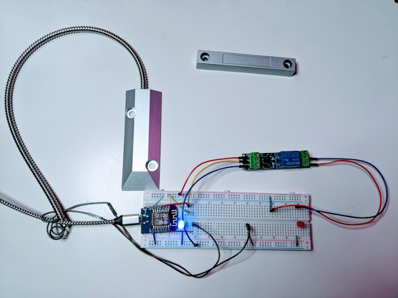
Figure 1: Clockwise from the bottom: The ESP8266 Wemos D1 mini clone wired into the breadboard, the reed switch plate, its accommpanying magnet, and the relay switch.
To test the module out, I wired it onto a breadboard, using it’s 3.3V pin to supply power to the top positive rail and hooked its ground pin to the lower negative rail. Hooking it up to the breadboard with only jumper wires is a bit finicky (I didn’t have a soldering iron at the time), so to confirm that everything was working I ran wires to hook a blue LED up between the power and ground. When everything was snug and the USB cable was plugged in, it lit up! Success!
Preparing the initial firmware
I used the ESPHome CLI wizard to generate my initial firmware configuration for
the device. The wizard prompts for various values needed for basic
functionality. In my case, I specify a name for my device (garage-door), the
microcontroller I’m using (ESP2866), the board I’m using (d1_mini), and some
WiFi credentials. Substitute in the credentials for the WiFi network your device
will connect to if you’re following along.
Review the contents of the generated YAML file, then connect the board to your computer via USB and run:
esphome run garage-door.yml
The CLI tool will generate and compile the code for you, then prompt you for the
device to install to. As this is the first time you’re installing the firmware,
you must select your USB device (in my case, on my linux machine, the device was
/dev/ttyUSB0 (USB2.0-Ser!)). You’ll see the logs as the device boots up and
connects to your network, and it’s up and running! Not doing much yet, but it is
there and discoverable!
Adding it to Home Assistant
Now that the device is running and discoverable on the network, it can be added
to Home Assistant. Home Assistant should detect the device on your network and
show it as a new device to add automatically in the Integrations tab of your
settings. Home Assistant will prompt for its password, which is in the api:
section of garage-door.yml (the same password that was set in the wizard). If
for some reason it doesn’t, click the “+ Add Integration” button, search for and
select “ESPHome”. Home Assistant then prompts for the connection settings (in my
case, the hostname was garage-door.local, and the default port is 6053). As
entities are added to the ESPHome configuration and uploaded to the device, they
will become available within Home Assistant.
Wiring up the garage door detector
The first thing I hooked up was the reed switch. One wire is joined to the D1
pin on the ESP, and the other to ground. In the ESPHome configuration, I added a
binary sensor for the switch, configuring the D1 for input with its pull-up
resistor enabled, which sets the D1 state to high normally. When the magnet is
within a couple inches of the switch plate, the switch will close the circuit,
triggering a state change from high to low on the ESP pin as the current can now
flow to the ground pin.
binary_sensor:
  - platform: gpio
    id: garage_door_sensor
    name: "Garage Door"
    device_class: garage_door
    pin:
      number: "D1"
      mode:
        input: true
        pullup: true
The binary sensor is using the gpio platform to read the D1 pin in input
mode with its pullup enabled. The id value will be used to reference the
sensor in other areas of the configuration, and the device_class is used to
inform Home Assistant that this device is monitoring a garage door.
I executed the esphome run command once again to load the new firmware, and
once it was up and running I was able to verify that the switch was working from
the logs as I moved the magnet up to and away from the switch plate.
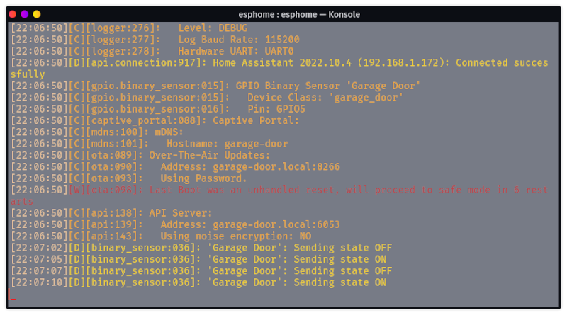
Figure 2: The ESPHome logs showing the door state updating.
I was also able to add the new sensor entity to my Home Assistant dashboard, which also updated as I moved the magnet!
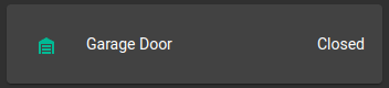
Figure 3: The garage door sensor card in Home Assistant.
Adding the garage door control switch
Next is the relay switch, which I will use to control the garage door so I can open or close it via the Home Assistant mobile app or any automations I decide to set up for it.
In the ESPHome configuration, I added a gpio switch using the D5 pin. Since
going to be activating this switch in a particular way within another control, I
marked it as internal so it can’t be activated manually via Home Assistant. I
then added a cover entity representing the garage door as a whole. This wraps
up the door sensor and door control into one neat package, and lets me specify
how the switch should be toggled to activate the door.
switch:
  - platform: gpio
    id: garage_door_switch
    name: "Garage Door Opener"
    pin: "D5"
    internal: true

cover:
  - platform: template
    name: "Garage Door"
    lambda: |-
      if (id(garage_door_sensor).state) {
        return COVER_OPEN;
      } else {
        return COVER_CLOSED;
      }
    open_action:
      - switch.turn_on: garage_door_switch
      - delay: 0.1s
      - switch.turn_off: garage_door_switch
    close_action:
      - switch.turn_on: garage_door_switch
      - delay: 0.1s
      - switch.turn_off: garage_door_switch
    stop_action:
      - switch.turn_on: garage_door_switch
      - delay: 0.1s
      - switch.turn_off: garage_door_switch
Because the garage has only one switch for opening, closing, and stopping the
door, the open_action, close_action, and stop_action are identical. To
trigger the mechanism, it activates the switch, pauses briefly, then deactivates
the switch. I used a lambda to interrogate the door sensor’s state to return
whether the “cover” is open or closed.
The switch uses three hookups to the ESP: One from the 3.3v pin, one from the
input wired to the D5 pin, and one to ground. To give it something to control
while testing in place of the garage door opener it’ll eventually connect to, I
set up a circuit with a red LED between the 3.3v power and ground lines, and
wired the relay switch in the middle. Because I only want the LED (door opener)
circuit closed when the switch is activated (i.e. a normally-open circuit), I
attached the LED circuit wires to the NO (Normally Open) and COM (Common)
leads on the far side of the switch.
Once this was done, I was able to activate the door control in Home Assistant and see the red LED toggled on and off!
By adding the cover entity to Home Assistant, I was also able to get this nifty control card!
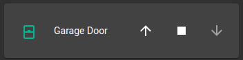
Figure 4: The garage door control card in Home Assistant.
Celebration!
Behold! The prototype works!
Hooking it all up for real
With the prototype sorted, it was time to put it together into something I could install!
Getting it soldered
I grabbed a perforated board and got to wiring and soldering everything
together, changing the pins I was using for the sensor and controller to make
them easier to route (now D5 and D2, respectively). For my first time
soldering electronics, it went pretty smoothly. Getting the wires soldered
together took a couple of tries and aren’t going to win any beauty contests, but
everything’s secure and working fine.
I also added a red status LED adjacent to the blue one I used for power that will flash when booting or in an error state.
status_led:
  pin: "D7"
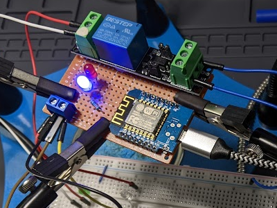
Figure 5: The top, all neatly connected to the board.
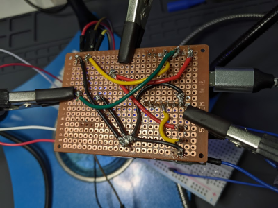
Figure 6: The bottom, all wired up.
Designing and printing an enclosure
With everything in place, I grabbed my calipers, measured everything, and hopped into FreeCAD. I put in some supports to hold the board up with some room underneath for the wires, and cut out holes in the sides where the usb power and external wires will attach to their screw mounts. I added small bumps on opposite inside walls to grab the edges of the board and hold it in place. I then made a lid that will slide in to the top, and opened holes in it for the LED to shine through and to provide access to the screws for the wire mounts. The lid also has a small bump for it to hold it in place when fully inserted.
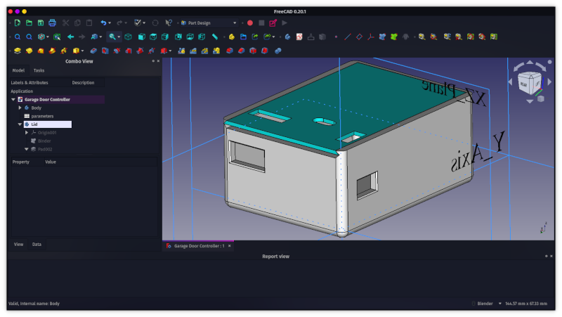
Figure 7: The completed design in FreeCAD.
There are pretty visible layer lines in the print, likely because I switched in a new roll of filament for this and didn’t dial it in first, but where this thing is going it doesn’t need to be gorgeous.
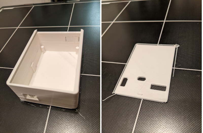
Figure 8: The case and lid freshly printed in white PLA.
The board popped right into place, nice and cozy in its new home. The openings lined up pretty well, though I did have to widen the USB opening a bit with an X-Acto knife so the cable would fit properly.
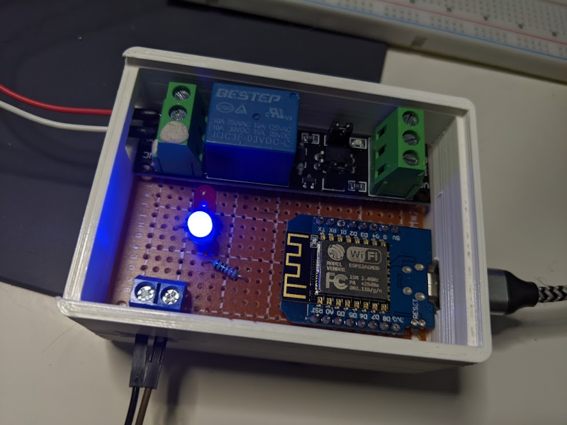
Figure 9: Snug in its new home!
The lid slid right in and locked in place just fine! The LEDs shine through their opening, and the screws are easy to get to and manipulate with a screwdriver.
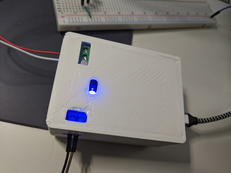
Figure 10: All tucked in with its lid!
I’m proud of my little creation and its pretty little case. Next up, installation!
Installation
Alright, time to get this thing into the garage! Getting this set up was pretty straightforward. I decided to install the reed switch sensor at the top of the garage door, screwing the sensor into wood above it and bolting the magnet onto the top of the metal door such that the magnet is positioned beside the sensor when the door is closed. Using my laptop, I was able to monitor the device and see that the switch did correctly register the door’s state.
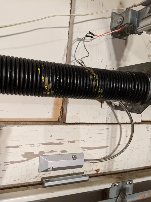
Figure 11: The switch is mounted to the wall with its wires running up to the rail, the magnet is mounted to the top of the door.
To connect everything together, I cut some lengths of bell wire to the distances
I needed, and got started. I ran a pair of wires from the switch from there to
the garage door opener, where I mounted the device to its frame with some ties.
I may attach it to the ceiling later so it’s prettier, but for now this works
just fine. I then wired the NO and COM connectors on the relay switch to the
two leftmost connectors in my garage door opener, which are the two connectors
shared with the wall garage door button.
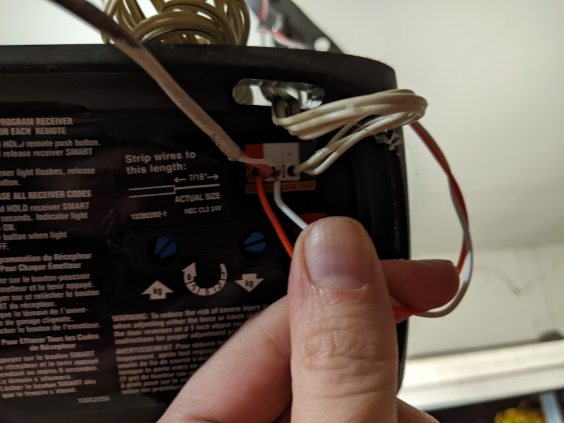
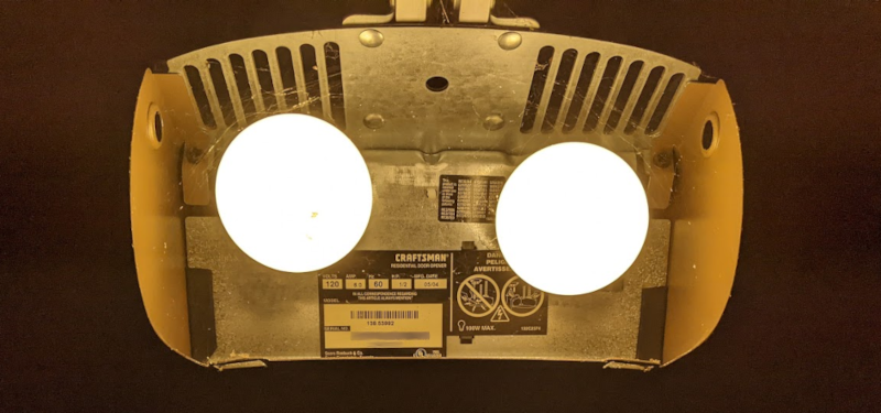
Figure 12: The wires were added to the garage door opener alongside the wall switch’s existing wires.
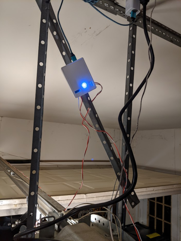
Figure 13: The device is mounted to the metal frame with ties, having drilled a couple holes into the back of the enclosure to loop them through.
With everything connected, I powered up my device with a USB power brick plugged into the outlet above the door opener, and… it worked! I was able to open and close the door using Home Assistant on my laptop or on my phone, and get feedback on whether the door was left open or closed!
Wrapping up
This was a really cool project! I’m super proud of it and very happy with the result, and I learned a great deal about building electronics along the way. I’m looking forward to finding more ways to make our home just a little bit smarter and easier for us to manage, and I expect I’ll have plenty of fun putting together even more electronic projects in the future!